
Zain Karsan
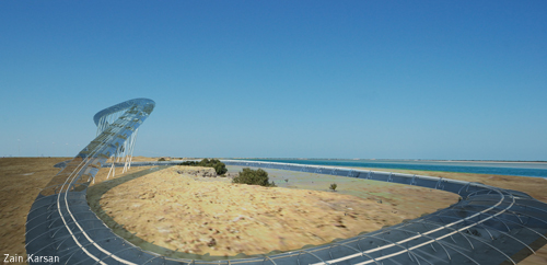
Designed for Site #2 in Abu Dhabi, between Saadiyat Island and Yas Island.
Design Submission for the 2010 Land Art Generator Initiative Design Competition
Artist’s descriptive text:
Infinity relies on the movement of water through a system of turbine rotors to generate electricity. The form is created from an array of curved hollow structural steel members in the shape of an ellipse, inscribed in which is the frame for the turbine rotors. The steel members are arrayed along a path that travels along the site in three dimensions. Half the structure is rooted in a concrete foundation.
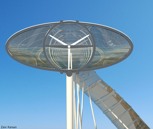
The installation is primarily clad in glass and a series of Fresnel lenses that focus light in specific places within the structure. The lenses intensify the sun’s rays and effectively heat a large volume of water within the structure. The water is heated to steam, which travels upwards through the structure, turning turbine rotors every 10 meters. The steam reaches the top of the structure, where the cladding is primarily glass, condenses and begins the cycle again.
The intent of Infinity is to question ideas about perception, the presence of light and its reflection off various surfaces that comprise the installation, water, steel members, is therefore integral to the aesthetic. The idea of transparency is another important feature of the project. Infinity attempts to challenge this concept through its shear size and expansive footprint. The site is almost completely inhabited by the structure, yet the motif of transparency remains through the installation’s materiality.
In another sense, the design attempts to be an alien object for in some way it is disconnected from its surroundings by its form. The installation essentially recreates its environment through its highly reflective skin, yet the world within the chamber created by the cladding is entirely different.
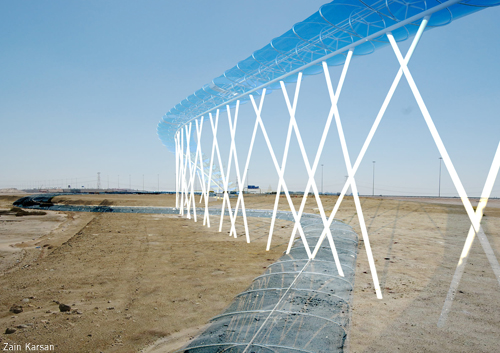
The first stage of construction is essentially a concrete foundation which provides the preliminary support for the structure. The next stage involves erecting the steel columns that support the elliptical members that generate the form of the installation. The support structure comprises of a series of steel members meet in various locations. This can be achieved with standard hollow structural sections welded to large cast steel joints and specialized intersecting members. The diagonal members achieve a level of stability through cross bracing. This is further reinforced with horizontal members that outline the path of the general form, and act as the spine of the installation.
The horizontal bracing also serves the purpose of a channel for electrical equipment to pass through. The horizontal members reach around the entire installation thus allowing each turbine to be connected through the horizontal members to meet at a central hub which can be accessed easily. The third stage involves connecting the elliptical steel members to the horizontal supports and the concrete foundation. The members that are connected to the concrete foundation directly are half ellipse shaped members that are connected with anchor bolts. The remaining elliptical members are welded to the horizontal supports. The turbines are welded to the circular members that are inscribed in the elliptical steel members.
The final stage involves attaching the glass and lens cladding between each elliptical steel member. The Fresnel lenses and glass are supported by a series of spider clamps that are arrayed around the elliptical steel member at 5 meter intervals.
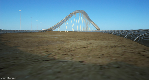
The mechanism that Infinity embodies is a system that cannot exist without the presence of light. Fresnel lenses that clad the steel structure at the ground level heat the volume of water that rests there. The heat initially induces a current but escalates to boil the water. Steam becomes the predominant phase within the system. The steam is forced to rise and travel in a specific direction. Fog catchers act as barriers for steam moving in the opposing direction. The steam travels upwards for the duration of the sunlit hours, condenses at the height of the structure, and travels downwards to begin the cycle again. This process can in some conditions, continue after sunlit hours for the concrete at the base of the structure, having absorbed heat throughout the day, can act in some way as a thermal mass and redistribute heat to the water. A current is induced and the cycle begins again the next day.
In addition, the steel members, being of a highly reflective polish, act as mirrors that redirect light that has bounced off the water. The turbine rotor is held in place by a metal plate that is welded to the circular steel section inscribed in the elliptical steel section. The projected energy production for the installation is upwards from 2.2 MW yearly.
The passage of vapor through the chamber occurs several times per day if a barrier is used at the height of installation. A fog catcher serves the purpose of preventing vapor from passing through without condensing first. As the vapor collects and condenses the water moves to the bottom of the structure and the cycle begins again.
[…] and condenses the water moves to the bottom of the structure and the cycle begins again. Source: Land Art Generator Initiative Reageer […]